Monitoring Devices Using SNMP in vRealize Operations 8.1
VMware’s vRealize Operations is an excellent monitoring, analytics, and self-driving IT operations platform that supports numerous applications and infrastructure systems out of the box. Management packs are available from both VMware and third-parties to extend these out of the box capabilities to a wide variety of additional applications and infrastructure systems. Unfortunately, management packs aren’t available for every hardware device that you might need to monitor. In these situations, monitoring via SNMP might be your only choice. Luckily for us, VMware has provided the vRealize Operations Management Pack for SNMP.
In the past, VMware’s vRealize Operations Management Pack of SNMP was limited to communication via SNMP version 1 (SNMPv1), making it not ideal for environments where security is a concern. However, with the introduction of the latest release of the vRealize Operations Management Pack for SNMP version 3.0, support has now been added to communicate with SNMP devices using SNMP version 3 (SNMPv3). Additionally, this release adds support for the auto-discovery of SNMP devices, built-in support for common MIBs, and custom MIBs, as well as the availability of predefined MIB statistics. In this post, I walk you through the process of configuring version 3.0 of the vRealize Operations Management Pack for SNMP to monitor a Cisco Nexus switch as well as creating custom alerts based on statistics collected from the device via SNMP.
Installation and Requirements
The VMware vSphere Operations Management Pack for SNMP 3.0 has one requirement:
- Requires VMware vRealize Operations 8.1 Advanced or Enterprise
The installation of the management pack follows the same procedure as all other management packs. Documentation for adding additional solutions can be found here: vRealize Operations 8.1 - Installing Optional Solutions - Add Solutions Wizard
MIBs
Any conversation about SNMP monitoring would not be complete without discussing MIBs (Management Information Bases). MIBs define the management information and structure of the information available via SNMP for a specific entity or device. Before monitoring any device via SNMP with vRealize Operations, the proper MIBs must available to the management pack to support the collection and processing of the SNMP information. To make it easy for us to get started with the management pack, VMware has included a collection of commonly utilized MIBs. The complete list of MIBs included in the management pack is provided in the List of MIBs in SNMP Adapter document included in the vRealize Operations Management Pack for SNMP Documentation.
If you find that your device’s MIBs are not included by default within the management pack, don’t worry. In addition to the included MIBs, VMware also provides us the ability to add additional MIBs to the management pack when needed. This process is straightforward and documented for us in the document titled: Loading Custom MIBs to vRealize Operations Manager for SNMP. Keep in mind that you must add the MIBs to all vRealize Operations Manager nodes in your cluster.
The Goal of this Walkthrough
For this walkthrough, I will demonstrate how to configure vRealize Operations to monitor a Cisco Nexus switch using multiple MIBs. After configuring vRealize Operations to collect data from the Nexus switch, we will define the symptoms and alerts that we wish to generate for our device. This walkthrough assumes your device is already configured to support SNMP connectivity.
If you have monitored devices in the past using other SNMP monitoring solutions, you may find that vRealize Operations doesn’t quite work the same as you would expect when it comes to configuring a device to be monitored via SNMP. Many SNMP monitoring tools consider the device being monitor as the base object. The tools then allow the user to define the MIBs applicable to the base device as well as which OIDs (Object Identifiers) to query for data collection. When you are ready to configure alerting, you define the OIDs and thresholds which trigger the alert for each device.
In the case of vRealize Operations, the SNMP MIB is considered the base object. In vRealize Operations terms, the MIB would define the “Object Type”. vRealize Operations then allows you to configure the devices applicable to the MIB. In the case where multiple MIBs apply to the same device in your environment, you would define the device under each MIB, resulting in multiple objects in vRealize Operations. If that doesn’t make sense to you right now, don’t worry. It took me a little while to grasp the concept as well. Hopefully, this concept becomes clearer as we walk through configuring the adapter.
Configuring the SNMP Adapter to Monitor a Device
As I mentioned, configurations for the SNMP management pack are defined by the MIB file. In the case of a Cisco Nexus switch, multiple MIBs apply to the device. To demonstrate collecting data from multiple MIBs, we will configure vRealize Operations to collect information from both the CISCO-ENTITY-FRU-CONTROL-MIB.mib and the CISCO-COMMON-MGMT-MIB.mib.
Defining Our SNMP Adapter Configurations
To get started, in vRealize Operations, select Administration from the top navigation menu, then select Other Accounts from the left side navigation menu. From the Accounts Type screen, select SNMP Adapter.
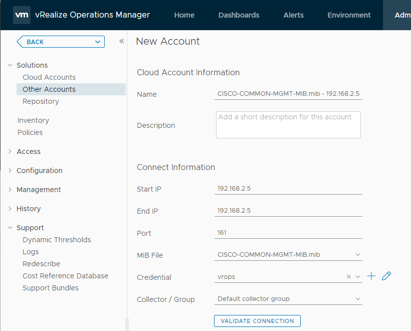
Next, we see the screen where we define our first MIB configuration for our device. For the Name field, we include the device(s) to be monitored as well as the MIB. Using descriptive names allows us to find our configurations easily in the future.
Under the Connect Information, we first provide a Start IP and End IP. These fields allow us to define a range of IP addresses to monitor using the MIB, or if we only have a single device, we specify the same IP address for both fields. For this walkthrough, I only have one switch to be monitored, so I specify the same IP address for both fields. The Port field by default is set to port 161, as this is the standard TCP port used for SNMP. If necessary, update this field to the port used by your device.
Next, we select the MIB file to use when collecting information from our device. In this walkthrough, we select CISCO-ENTITY-FRU-CONTROL-MIB.mib from the list. Since this is our first time configuring the SNMP Adapter, we need to create a new SNMP credential for the Credential field. Click on the + sign to the right of the field. On the resulting Manage Credential dialog, depending on the version of SNMP you are using to connect to your device, select either SNMPv2c Credential or SNMPv3 Credential and provide the required details for you SNMP connection credential. After you’ve created your credential, make sure that it is selected in the Credential field. Click the Validate Connection button to validate that vRealize Operations can successfully communicate with your device using the SNMP configuration that you provided. If the validation test is successful, click the Add button to save the configuration.
Now you might say: “Wait a second, didn’t you say you’d be monitoring the device using two MIBs?” You are correct. That’s why we must repeat this process a second time, but when entering the information, we select the CISCO-COMMON-MGMT-MIB.mib for the MIB File field. When finished, vRealize Operations lists two SNMP Adapter configurations for our device.
Configure our vRealize Operations Policy to Collect Data
Even though we have defined our SNMP Adapter configuration for our MIB files and devices, we still must configure vRealize Operations to collect the data for the specific OIDs defined within the MIB files that we are interested in monitoring. We accomplish this by grouping our newly created MIB device objects into a custom group and assigning a custom monitoring policy to this group. For this example, we want to monitor the following:
- Power Supply State - cefcFRUPowerOperStatus - OID: 1.3.6.1.4.1.9.9.117.1.1.2.1.2
- Generate an alert for values other than 2 (on)
- Fan State - cefcFanTrayOperStatus - OID: 1.3.6.1.4.1.9.9.117.1.4.1.1.1
- Generate an alert for the values: 1 (unknown), 3 (powered down), and 4 (warning)
- Forced Encryption for SNMPv3 Users - ccmCommonUsersGlobalEnforcePriv - OID: 1.3.6.1.4.1.9.9.443.1.1.3
- Alert if the value is 2 (false)
Create the Custom Group
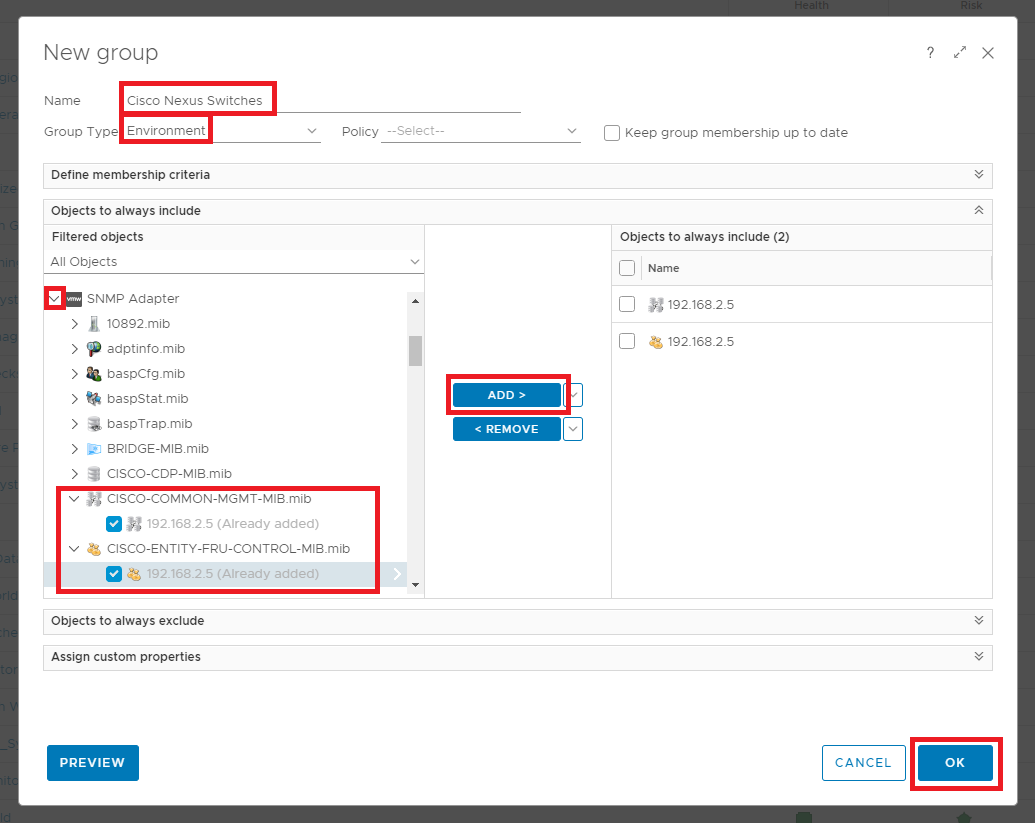
The process of creating a custom group within vRealize Operations is very straightforward. The procedure is documented within the vRealize Operations documentation titled User Scenario: Creating Custom Object Groups. For this walkthrough, I have decided to create the custom group using the “Objects to always include” criteria instead of defining dynamic rules. Using this method allows me absolute control over which devices data is collected. To get started, within vRealize Operations, click on Environment on the top navigation menu. On the resulting Environment Overview page, the Custom Groups tab is selected by default. Click the Add button to begin creating the new custom group.
In the Name field, provide a descriptive name. In my case, I use “Cisco Nexus Switches”. Next, for the Group Type field, we select “Environment”. If you wish to use something else, you can follow the documentation link I provided above to define custom Group Types. Since we are not using dynamic criteria to populate our Custom Group, you can ignore the Keep group membership up to date checkbox. Next, we expand the section “Objects to always include”, expand the SNMP Adapter, then expand the entries for each of my MIBs. The IP address for the device is listed under each MIB. We place a checkmark next to both entires and click the Add button to include them in the group. Next, click OK to save the group.
Now that we’ve defined our Custom Group, the next step in the process is to create a new Policy that will collect data for the OIDs that we are interested in analyzing. The policy will then be applied to our Custom Group.
Define the Monitoring Policy
The next step in our journey to monitor our devices using SNMP is to define a new Policy object within vRealize Operations. The vRealize Operations documentation titled Using the Monitoring Policy Workspace to Create and Modify Operational Policies provides an overview of the process. We will quickly walk through the process as it applies to our SNMP monitoring scenario.
To get started, select Administration from the top navigation menu, then select Policies from the left side navigation menu. The resulting page has two tabs at the top. Select the Policy Library tab and click the Add button to start the process of creating a new policy.
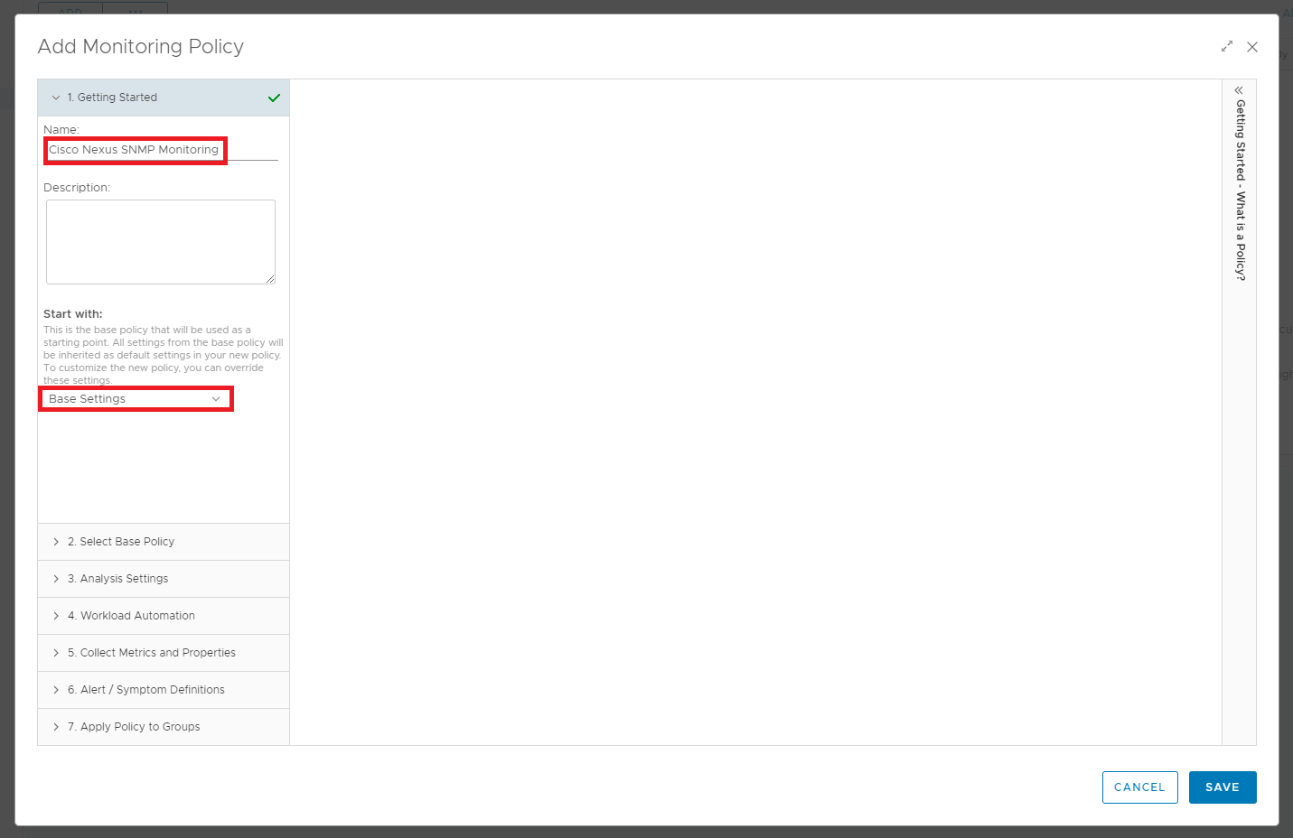
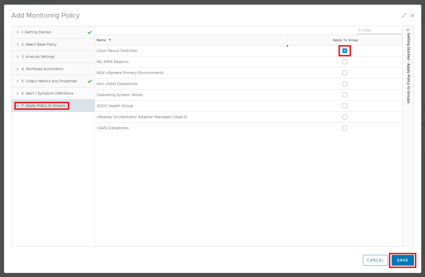
Three sections within the Add Monitoring Policy wizard concern us in this scenario. First, within section 1. Getting Started, we must define a Name, an optional Description for our policy, and the Start with field, which defines the base policy to use as the starting point for this policy. I chose to name the policy “Cisco Nexus SNMP Monitoring”. I chose “Base Settings” as the Start with policy for this new policy.
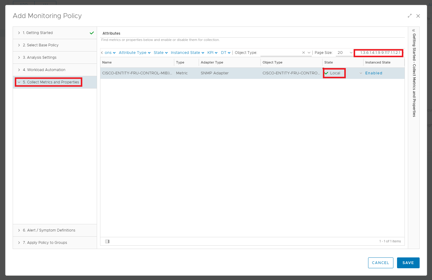
The next section of the wizard that we need to configure is 5. Collect Metrics and Properties. This section of the wizard allows us to define the OIDs that we wish to monitor. The wizard provides several options at the top of the form to filter the Attributes list, but the most straightforward option since we know the OIDs is to search by OID. After finding the attribute for the OID value, update the State field to “Local”. Repeat this step for each OID that we plan to monitor.
The final section of the wizard that we need to configure is the 7. Apply Policy to Groups section. This screen provides a list of custom group objects that exist within vRealize Operations. Select the “Cisco Nexus Switches” group that we previously created. Selecting our custom group here applies the settings of this policy to our custom group. Finally, click the SAVE button to save our new policy object.
Verify that Data is Being Collected
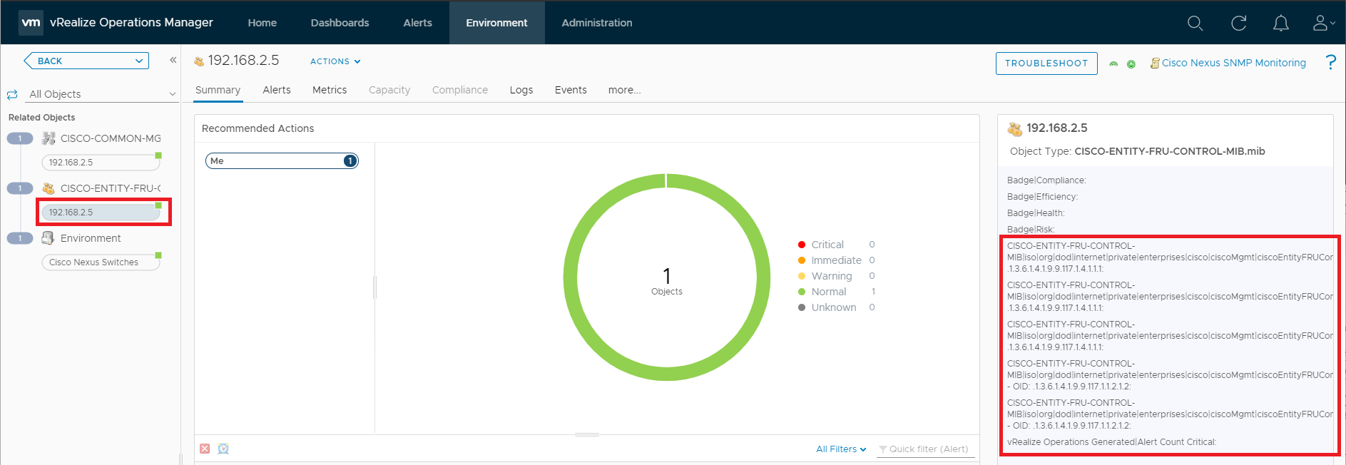
Now that we have our policy configured and applied to our custom group, we can verify that the SNMP adapter is receiving data. A quick and easy way to do this is to select the “Cisco Nexus Switches” custom group we created earlier. After selecting the group, on the left side navigation bar, both of our MIBs are listed. Clicking on the name of each MIB expands the entry to show the child object. Click on each child object and verify that the Summary screen to the right shows data, as shown below.
Define the Alert Symptoms
As previously mentioned, the items we wish to alert on for the Nexus switch are:
- Power Supply State - cefcFRUPowerOperStatus - OID: 1.3.6.1.4.1.9.9.117.1.1.2.1.2
- Generate an alert for values other than 2 (on)
- Fan State - cefcFanTrayOperStatus - OID: 1.3.6.1.4.1.9.9.117.1.4.1.1.1
- Generate an alert for the values: 1 (unknown), 3 (powered down), and 4 (warning)
- Forced Encryption for SNMPv3 Users - ccmCommonUsersGlobalEnforcePriv - OID: 1.3.6.1.4.1.9.9.443.1.1.3
- Alert if the value is 2 (false)
To get started with creating our Symptom definitions, click on Alerts from the top navigation bar. Next, click on Symptom Definitions from the left side, then click the Add button to begin defining the first symptom.
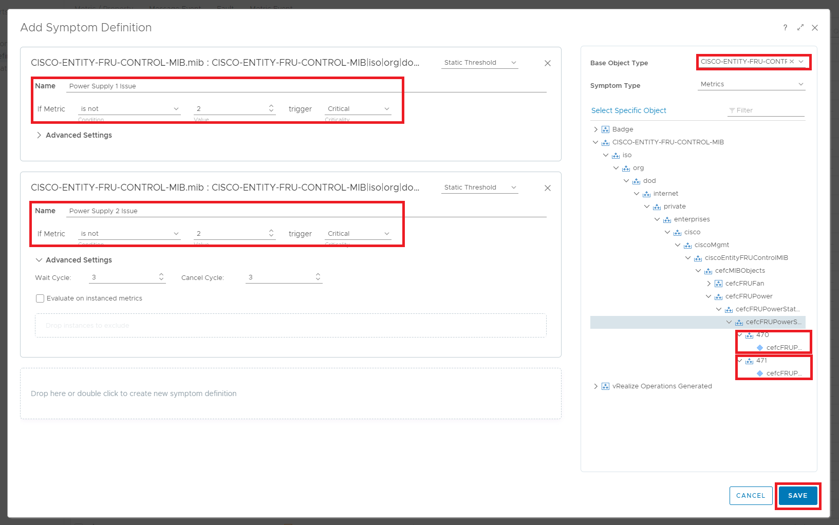
On the resulting Add Symptom Definition wizard, we first must select the Base Object Type for our symptom. To create our first symptom regarding the Nexus switch’s power supply, we select “CISCO-ENTITY-FRU-CONTROL-MIB.mib” for the Base Object Type. Next, we expand out the metric tree to find the metric entries for the cefcFRUPowerOperStatus OID. Notice that there are two entries under the cefcFRUPowerOperStatus. Expanding each numeric value provides us the metric to be checked for our symptoms. In the case of the power supplies, anytime a power supply returns a state value other than “2”, we should generate an alert. After we have filled in the proper information, click the Save button to save the symptoms.
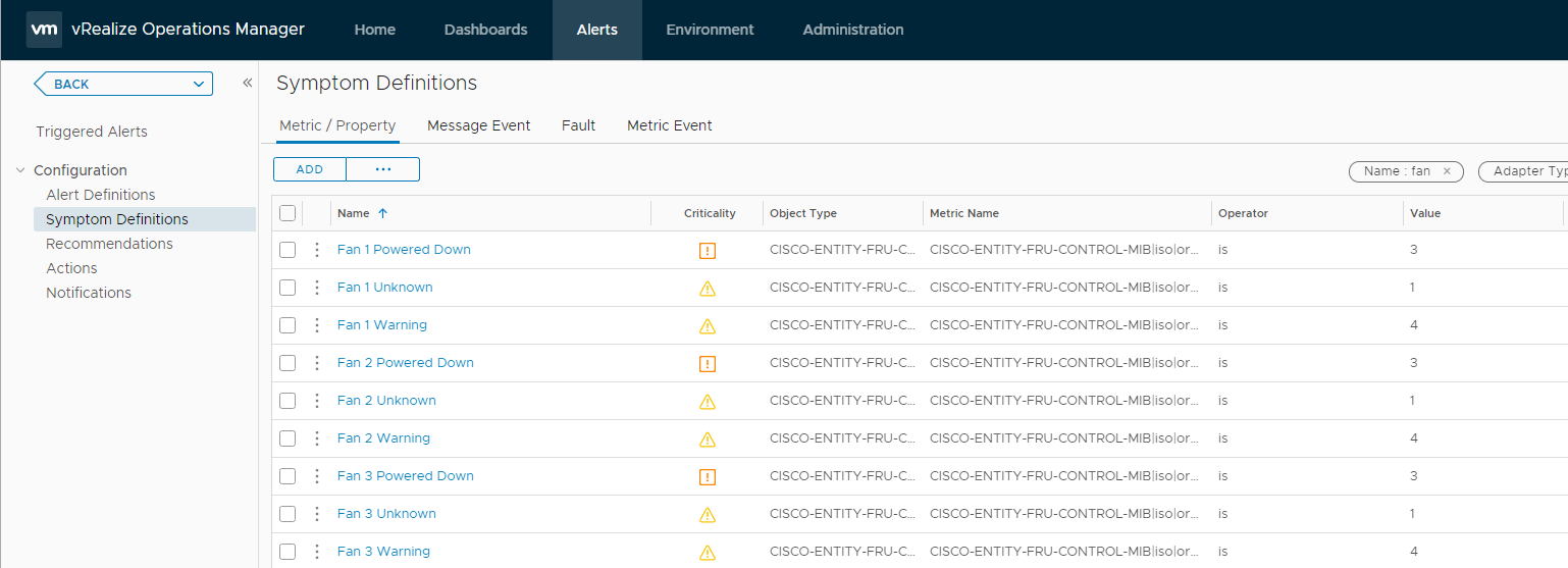
We repeat this process two more times for the cefcFanTrayOperStatus and ccmCommonUsersGlobalEnforcePriv checks. After creating all the symptoms, we should have a list that appears similar to the following.
Creating the Alert Definitions
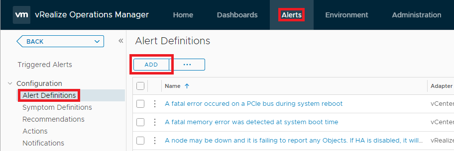
With our symptoms defined based on the data collected via SNMP, we now define our Alert objects within vRealize Operations. To do this, again, select Alerts from the top navigation bar, and then select Alert Definitions from the left side. Click the Add button to begin creating our first Alert object.
The Create Alert Definition wizard is loaded, which contains five sections. For the first section titled 1- Alert, we enter a name for the alert and select the MIB as the Base Object Type. I entered “Cisco Nexus Power Supply Issue”.
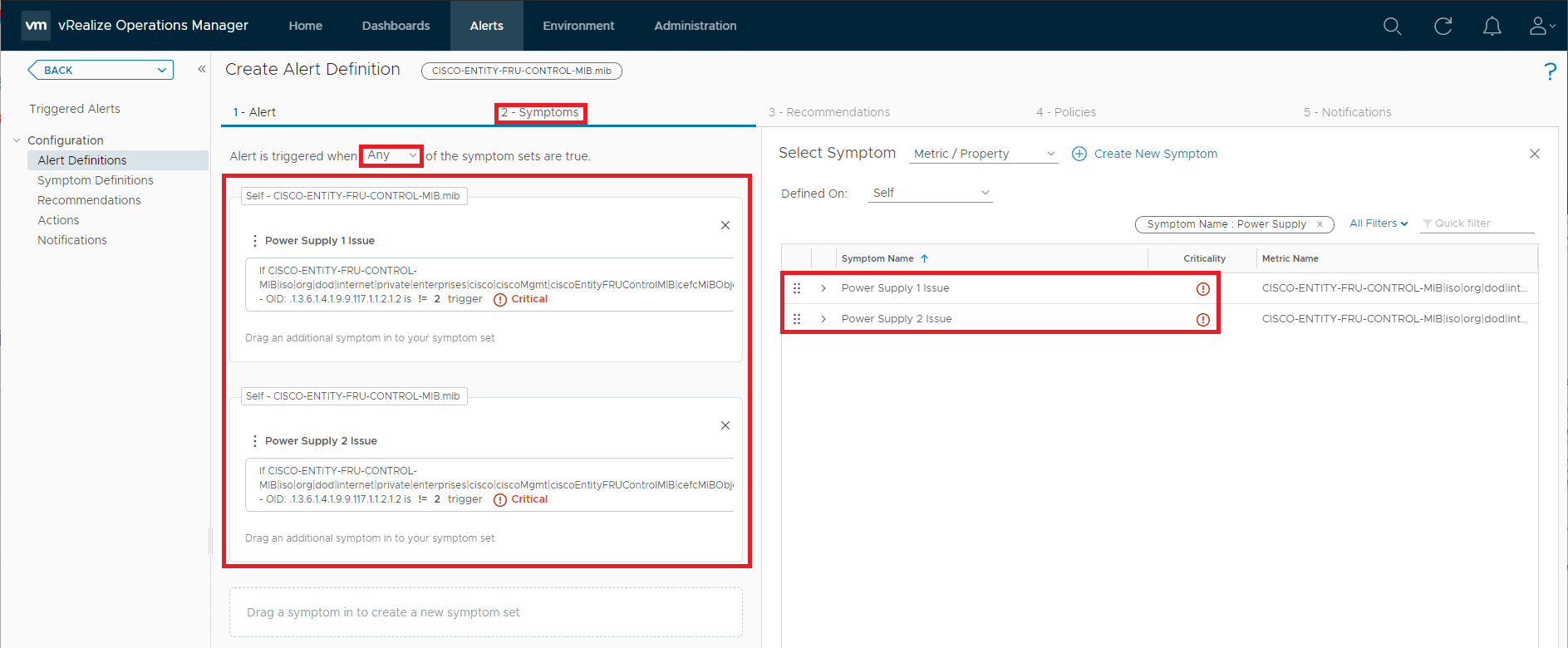
Next, under section 2 - Symptoms, we first define that the Alert is triggered when “Any” of the symptoms are true. Next, drag the symptoms we previously created regarding the Nexus switch power supplies from the right side of the screen to the left side.
Skip the section titled 3 - Recommendations as we did not create any recommendations to be included in our alert. In section 4 - Policies, select the “Cisco Nexus SNMP Monitoring” policy that we previously created to apply these alerts to the devices monitored under the policy.
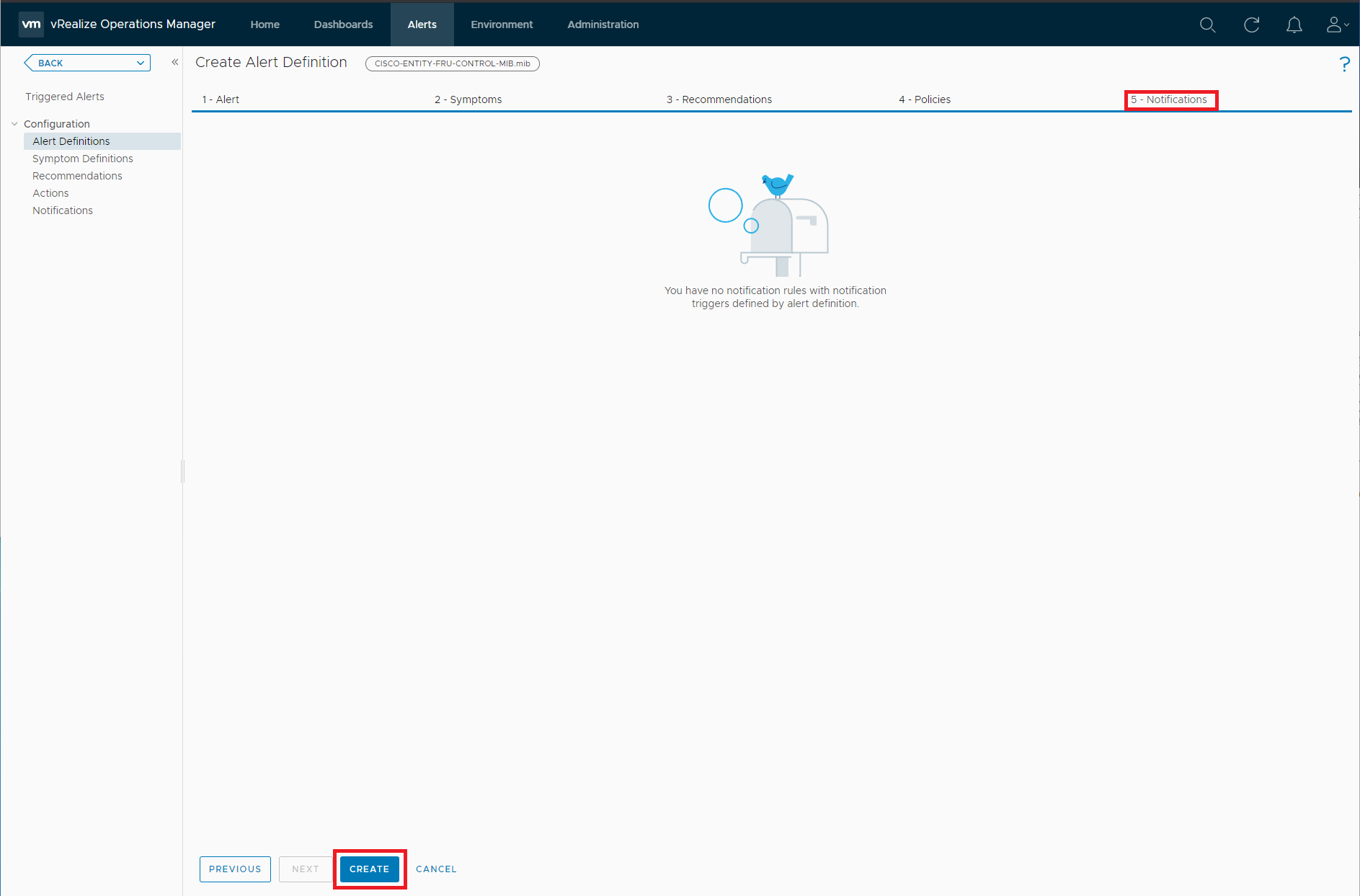
Skip the section titled 5 - Notifications as we do not have any notifications rules defined at this time. Click the Create button to finish the creation of the new Alert object.
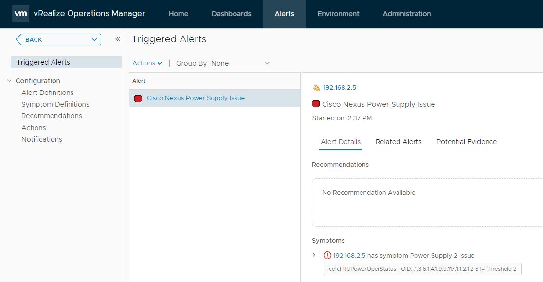
We repeat this process two more times to create alerts for the fan and SNMP encryption symptoms. That’s all there is to it. To verify that the alerts are working (based on the fact that I know one of my power supplies is unplugged), we view our alerts and filter for alerts triggered on “192.168.2.5”. As you see, the alert has been triggered as expected.
Conclusion
Version 3.0 of the vRealize Operations Management Pack of SNMP is a vast improvement over the previous releases, and I’m thrilled to see the added support for SNMPv3. The ability to monitor any SNMP based device using vRealize Operations adds several new use cases to the product.
However, I remain confused and disappointed regarding how the plugin implements object creation. In the case of my Cisco Nexus switch, several MIBs apply to the switch. Each time I configure a new MIB to connect and pull information from my switch, vRealize Operations creates a new entity to represent my switch as it relates to the MIB. Each of the new entities created is a distinct entity within vRealize Operations and has no relationship to one another. This prevents me from seeing a holistic view of the data, symptoms, and alerts that apply to the physical switch. I hope that a future release of the vRealize Operations Management Pack of SNMP addresses this issue and allows for the consolidation of all SNMP data related to a single device to be visible under one entity in vRealize Operations.
See Also
- VMware Introduces New vRealize Cloud Universal -
- Automated Snapshot Cleanup with VMware Aria Operations -
- Add Custom Properties to vRealize Operations Using the REST API and vRealize Orchestrator -
- Automated Alert Remediation in vRealize Operations 7.x using vRealize Orchestrator -
- VMware vRealize Automation 8.2 – Patch 1 Released -
Search
Get Notified of Future Posts
Recent Posts


